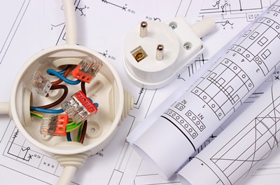
Diagrams are provided with many electrical devices. The diagrams aid in reading and interpreting the quantities in a circuit. An electrician should have knowledge and understanding in reading these diagrams. Reading electrical circuit diagrams may prove to be difficult, but here are some of the key points to focus on.
Table of Contents
-
- Electrical schematics
- Electrical knowledge
- The correlation to the real circuit parts
- The Circuit function
- Familiarisation with SI units
- The Polarity
Electrical schematics
The electrical schematics are read from left to right or from top to bottom.
This is important to get right, as the signal direction indicates the flow of current in the circuit. It is then easy for a user to understand when there is a change in the course of the circuit.
Electrical knowledge
A number of varieties of schematic symbols exist for representing real devices or wires in a circuit. The expertise to understand these electrical diagrams and be able to read them is key, as a wrong reading of these details results in wrong interpretation.
Straight lines represent wires, the wires are used to connect different peripherals in a circuit. This may include bulbs, switches, etc. A triangle represents ground or service, it indicates the area of operation for a circuit. A zigzag diagram represents resistors. They act to prevent extreme current flow in a circuit.
Resistance is determined by the value used in current scale. In electrical diagrams, capacitors are represented by parallel lines attached to the main circuit. The capacitors are used to draw the sound and the rapid change in signal and drain it to the ground.
The correlation to the real circuit parts
Refer to the material to understand the actual values of the capacitors as well the resistors.
It is also recommended to consult the manufacturer’s manual for any electrical device. It will help you know the actual value in any active device.
The Circuit function
Each device has a particular manufacturer’s data manual. Electricals and electronics apply Ohms Law to calculate quantities like resistance, current and voltage. Current is defined as the electromotive force (the flow of electrons in a closed circuit) the formulae for calculating current, voltage and resistance is V=IR.
Familiarisation with SI units
Every discipline in science uses a standard chart for SI units, these units are recognised worldwide. However, many electricians fail to understand the importance of the units. It’s a duty for every electrical technician to know how to read the chart. It is beneficial in understanding the unit of every electrical quantity.
Electrical quantities are measured using the SI units. Thus, each unit is unique to an individual quantity.
The Polarity
Some circuits have polarity. They carry a positive charge and a negative charge. Understanding polarity is important. You should always follow the law of ‘like charges repel’ and ‘unlike charges attract’. So, negative to positive and vice versa. Most symbols have polarity signs included, thus, it’s easy to identify either terminal.

 same day delivery
 20,000+ stock, great deals!
 Experienced staff on hand
